Frequently Asked Questions
Regulation
Regulation includes both the input and the output of the transformer.
These are called " Line Regulation " and " Load Regulation."
Line Regulation
Line Regulation is the variation of main voltage, applied to the primary winding of the transformer. The changing of voltage on the primary winding results in a change of a voltage on secondary side with the same percent (with the exception of CVT - Constant Voltage Transformers).
For example, if the main voltage of 120 volts varies on + - 10 % (from 108V up to 132V), on the transformer with a output voltage of 12V, it will change the same + - 10% (from 10.8V up to 13.8V)
If Line Regulation is not determined by the customer, we use standard
+ - 10 %.
Load Regulation
Load Regulation is a change in output voltage with a change of load.
If: Vout (NL) - output voltage at no load
Vout (FL) - output voltage at full load
That Regulation =[ Vout (NL) -Vout (FL) /Vout (FL)] X 100 %
Vout decreases proportionally with the increase of the load.
If loading is constant, the target voltage of the transformer is defined
at complete loading,
For example Vout = 12V at 1A or Vout = 12V at 12Ohm.
Also, if the loading variable is to exceed the output voltage due to load reduction, it is necessary to define the Regulation or as much of it as possible to allow the target voltage to have minimal loading.
It is necessary to point out, the improvement that the Regulation requires as a rule, to increase the dimensions of the transformer. So, from two transformers of identical capacity, with other things being equal (material, form of the core, winding wires, and frequency of a current, etc.) the Regulation is better with the larger one.
The transformer’s Regulation is improved as the capacity is increased. In the diagram below, the curve shows the dependence of regulation from capacity for transformers, executed on EI cores, working on a frequency of 60 Hz, and designed for overheating at 50 degrees Celsius.
Load regulation vs. output power for 60Hz ordinary transformer
Ambient Temperature
Ambient temperature it is temperature measured on distance 8-10mm from Transformer.
Temperature Rise
Temperature Rise is the difference of temperature between the surface
or coil and the ambient temperature.
Temperature Rise of coil is ‚Tcoil = Tcoil - Ta
Temperature Rise of surface is ‚Tsurf. = Tsurf - Ta
Where Tcoil – internal temperature of coil measured by internal
thermocouple or by resistance method.
Tsurf. – Temperature of core measured by thermocouple.
Insulation class
Insulation systems include all isolation materials used in manufacture
of transformers such as bobbins,
sheet film, film tape insulations, varnish covering of wires, varnish
for impregnation etc.
The temperature stability each component should not be lower than the
temperature value for specific insulation classes. See the table below.
UL and CSA Temperature rating at ambient (25°C)
| Maximum Rise Above Ambient, °C | ||
| Insulation Class | Thermocouple method |
Resistance method |
| 105 (A) | 65 | 75 |
| 130 (B) | 85 | 95 |
| 155 (F) | 110 | 120 |
| 180 (H) | 125 | 135 |
Active loading
Active loading concerns all kinds of incandescent electric lamps, heating elements, resistors.
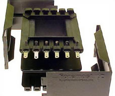
Print Circuits Pins
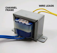
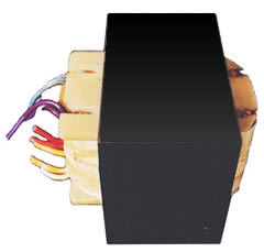
Wire Leads
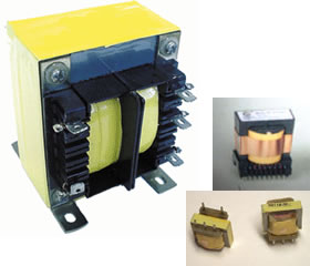
Solder terminals
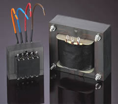
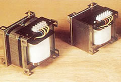
Terminal Blocks
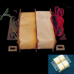
Magnet Wire leads
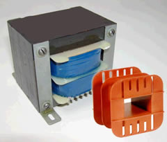
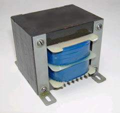
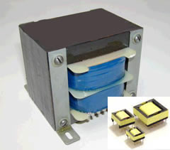
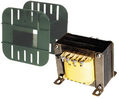
Channel Frame
Bracket
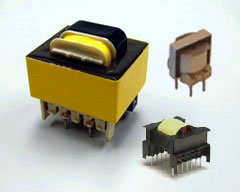
PCB
Open Mount
Vertical Mounting
Horizontal Mounting
Flat
VDE
One Section

Two Sections